

2017-10-16
The right torque in the right place
Optimal selection and installation of backstops for conveyor systems
If freewheels are deployed as backstops, they are entirely devoted to operational and work safety. In the drive systems of conveyor systems, they prevent the reverse movement of conveyor belts when maintenance work is being carried out, in emergency-stop situations or during power failures. In this specialist article, the different types of backstops available and what you need to take into consideration when selecting and installing them are discussed by someone who knows what he is talking about. Author Thomas Heubach was not only chairman of the Forschungsvereinigung Antriebstechnik (FVA) research team for more than 15 years, he is also the division head at RINGSPANN, the worldwide leading manufacturer of industrial freewheels.
When the drive systems of conveyor belt systems or bucket conveyors are in operation, they are usually being used to quickly and safely transport bulk goods upwards. All plant operators are understandably united in their desire for problem-free 24/7 continuous operation. The only reasons these systems should be brought to a halt are for maintenance purposes or in emergencies. In such cases, backstops (or brakes) prevent the reverse movement of the conveyor belts – if the power fails or the motor is switched off. The installation location of the backstops (BS) depends on the design of a conveyor system. In small and medium-sized systems it is common to place them directly on the motors or in the gearboxes. In large conveyor systems, large BS are often mounted onto the conveying shaft between the pedestal bearing and the output shaft of the gearbox.
PART I
Fast or slowly running freewheel
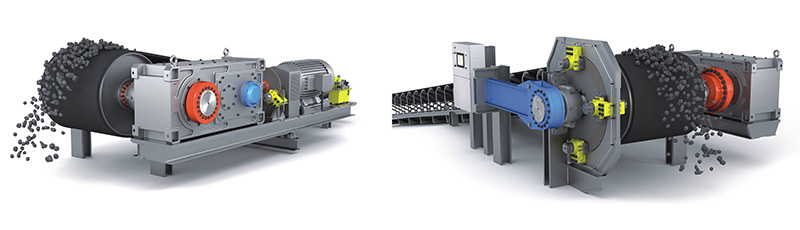
The normal operating mode of a backstop is the freewheeling operation. Torque transmission only takes place when the conveyor speed returns to zero from the nominal speed. Backstops should therefore run wear-free in normal operation and achieve as long a service life as possible. Wear-free running BS therefore use special clamping pieces with a lift-off function. The sprag lift-off is based on the impact of the centrifugal force. Backstops of this type are referred to as fast running backstops. As can be seen in figure 1 (left), they are installed on the first or central drive shaft, or on the motor shaft. On the output shaft of a drive gearing, the nominal speed is however not enough to activate the lift-off function. Backstops mounted here therefore employ hydrodynamic oil films to extend the service life. They are described as slowly running backstops (figure 1, right).
Modern conveyor systems are often operated with multiple drives that can be switched off individually in phases of lower energy requirements and which – in the event of the failure of one drive – protect each other. The BS are selected here by way of the various installation positions that are however respectively subject to different torque requirements. It is therefore essential for large conveyor systems with multiple drives and backstops to have a perfectly coordinated load distribution system. In this case, selecting the right BS is a complex task.
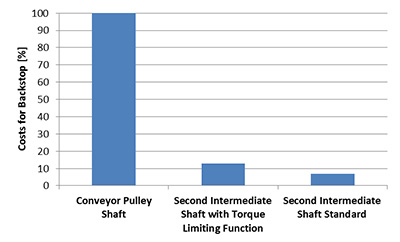
The dynamic behaviour of the BS – particularly in inclined conveyor belts – is a key factor in their selection. Numerous analyses have hereby shown that the installation position of an BS has a large influence on the required torque – and the total operating costs: While the torque requirement behaves linear to the gear ratios, the costs for the BS largely do not behave linear. As can be seen in figure 2, the cost expenditure as a percentage varies significantly depending on the installation position. In the example used here, an BS with sprag lift-off on the second intermediate shaft of the gearbox is approx. 90 percent cheaper than a slowly running BS on the conveyor pulley shaft. The fast running version is also more economical; the sprag lift-off also ensures its wear-free operation and long service life.
Conveyor systems with single drives
Let us first consider the example of a standard selection of an BS for a system with a single drive: Here, due to the non-linear torsion spring characteristics of the clamping elements (in the BS) in the moment of the torque transmission, and due to the dynamic behaviour of all remaining elements in the drivetrain, a selection factor must be determined. Depending on the requirement, BS manufacturers recommend a factor of between 2.6 and 3.5 times the maximum torque of an BS. This value is set conservatively and depends on different variables that have a significant influence on the dynamic behaviour of the entire system – such as the belt inclination and the efficiency of the drive system. Modern analysis programs such as DRESP for torsional oscillations – developed by the German Forschungsvereinigung Antriebstechnik (FVA) – now make it possible to simulate the process of a complete drive system with all real inertia, stiffness and transmissions. This also makes it possible to apply forces, torque characteristics and specific effects to the calculation models.
Two locks in the DRESP simulation
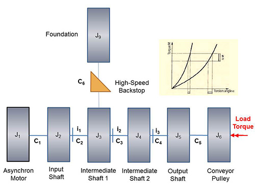
Figure 3 shows the DRESP model of a single drive assembly group, where a fast running BS with sprag lift-off is mounted onto the first intermediate shaft of the gearbox. While the lift-off function is not relevant for the calculation of its torque, the non-linear torsional stiffness influences the entire dynamics of the drive group. This aspect is incorporated into the calculation – just like all other available inertias and stiffness.
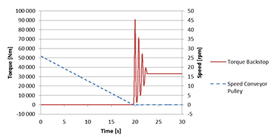
In the example, a load torque ML of 650,000 Nm is applied to the conveyor pulley. In the initial state, the pulley turns at a nominal speed of 26 rpm while all other rotating parts turn at a speed according to the gear ratios. Figure 4 shows the calculated braking of the drum and the resulting load in the BS: The speed of the conveyor pulley slowly falls from the nominal speed back to 0 rpm, and the BS must hold the load after 19 seconds. It is hereby subject to a peak torque of 91,000 Nm. The system “pulses” three to four times before it stands and the BS holds the nominal torque of the load torque ML. In this example, the ratio between peak and nominal torque is 2.75. The peak torque depends on the stiffness of all components. (It can be greater if Elastomer clutches or other non-linear components are installed.)
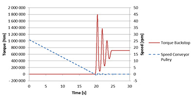
For the second simulation, a slowly running BS is mounted directly onto the conveyor pulley (J6) – with the same system design as before. The result can be seen in figure 5: Once again, the system stops after 19 seconds; now, however, the peak torque is 1,800,000 Nm. The ratio between peak and nominal torque in this case amounts to 2.6. This means that the dynamic behaviour roughly corresponds to that of the arrangement with a fast running BS; the selection factor is also similar. One advantage of the slowly running BS, however, is that the drive gearing is not under tension after the system stop. It is – as previously mentioned – much more expensive.
PART II
Conveyor systems with multiple drives
When selecting BS for conveyor systems with multiple drives, it must be taken into consideration that, in the event of a stopping procedure, the torques are distributed unevenly to the individual drives and BSs. Primarily, in the event of a plant standstill, the entire return torque can, as a result of the differences in the radial play and the elasticity of the affected drives, lie on a single BS! In systems that are equipped with a standard BS, the individual drive gearing and the BS must therefore be designed in such a manner that they can take up the entire return torque of the conveyor system to ensure its operational safety. A load distribution system that protects the gearbox against overload and dynamic peak torques during the locking process is therefore extremely important for conveyor belts with multiple drives.
The problem of the uneven torque distribution during a locking process can however also be solved by using BS with torque limiters (TL). The torque limiting integrated in the backstop temporarily slips as soon as the target torque (MR) is exceeded – until the remaining BS take effect in succession. This way the entire return torque of the conveyor system is distributed across the individual drive gearing and BSs. Dynamic peak torques are reduced and the drive gearing are protected.
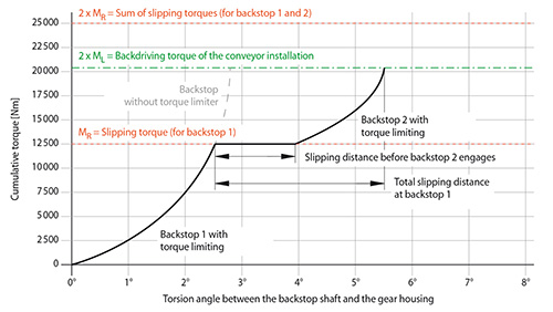
This “collaborative” load distribution is shown in figure 6: If the system stops, BS 1 holds a share of the load until the slipping torque (MR) of the torque limiter is reached. The BS 1 slips to compensate any play, elasticity and friction differences before the BS 2 takes up the remaining load share. Dynamic peak torques do not occur since the torque limiter in BS 2 also slips at the target torque. The diagram also shows that a backstop without a TL needs to be much higher to hold the torque of reverse operation. The user must take the dynamic effects into consideration: The use of backstops without a TL necessitates the use of backstops with larger torque capacities.
Backstop manufacturers recommend a selection factor of 1.2 for backstops with a TL. This selection factor is much lower than that of backstops without this feature since dynamic peaks are avoided and reduced thanks to temporary slipping.
Fast running backstop with TL in a dual drive system
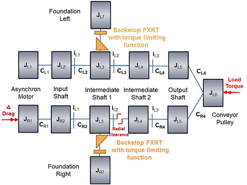
Figure 7 shows the DRESP analysis model of a drive group with two drivetrains. In contrast to the illustration of the single drive assembly group, here a TL is implemented with a set slipping torque of 42,000 Nm between the backstop and the surrounding construction. Two drivetrains (left/right) are in contact with the conveyor pulley and a load torque of 1,300,000 Nm is simulated on the drum. A small radial play and low drag torque are applied to the drive group on the right-hand side. The radial play generates a lag due to the drag torque. This corresponds to real events since the friction of two drivetrains is never the same. As has already been shown in the example of the single drive, the conveyor pulley initially turns at a nominal speed of 26 rpm, and the remaining components turn at a speed according to the gear ratio.
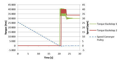
The result is shown in figure 8: Like before, the system stops after 19 seconds. The BS on the left-hand side of the drive group holds the load until the torque limiter reaches the slipping torque. It slips roughly 0.5 seconds until the right side has balanced out the radial play and the second BS is triggered. As a result of the dynamic energy, both BS slip together and lower the dynamic peak torques in the drive group. The backstops therefore share the load. A slight difference in the holding torque can however be seen when the system finally comes to a standstill.
The simulation also makes it possible to see the importance of the load distribution since it shows the uneven load distribution at the beginning of the locking process. Without load distribution, the drive gearing and BS must be selected in such a manner that they hold the entire load, including the dynamic peak torques of both drive groups.
The simulation makes it clear that BS with torque limiters realise an effective load distribution. This is absolutely necessary in order to reduce the peak torques in multiple drives. As described, the use of fast running BS already reduces the total operating costs. The use of BS with torque limiting serves to further reduce costs and at the same time increase the operational safety of the drive system.
PART III
Quality characteristics for backstops with TL
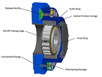
The harsh deployment and surrounding conditions at conveyor systems – particularly in the bulk goods conveying of iron ore, coal, copper and similar – place high demands upon BS design. At the same time, the user expects extremely reliable structures that can be operated for many years without requiring the use of special tools or specialist equipment. The relationship between torque capacity and construction size is a central factor in the development of modern BS.
The latest compact design of an BS with torque limiting is shown in figure 9. The inner ring with the clamping piece cage is hereby identical with the inner parts of a fast running standard BS with a lift-off function. This means that the BS runs wear-free in freewheeling operation and thus achieves a long service life. The outer ring is situated between the friction linings that are in mesh with the housing through disc springs. As a result, this BS type can transmit torques up to the pre-set slipping torque – determined by the force of the springs, the friction coefficient and the friction radius of the friction linings. In general, the following applies: This torque is always lower than the maximum torque capacity of the BS.
The friction linings must be designed for a high surface pressure – also to reduce the dimensions of the TL. In order to achieve soft torque limiting between holding and slipping, a friction material should be preferred in which the static and dynamic values of the friction coefficient are similar. Although there are only relatively small relative movements of the outer ring result in the BS when achieving the slipping torques, the friction linings are indeed subject to wear in the long term. Strong resistance to wear is however a necessity for a long service life and a high degree of operational safety. Carbon is therefore particularly well suited as a material for the friction linings. Carbon’s figures in terms of the dynamic friction and the permissible surface pressure in comparison to organic or sintered materials are excellent. And, since friction linings enable higher slipping torques, it is possible to double the torque capacity of the BS while keeping its external dimensions!
Release function – purely mechanical
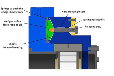
In normal operation, the BS is in freewheeling operation and the clamping pieces turn without contact to the outer ring. The conveyor belt occasionally comes to a stop, and the BS prevents the reverse movement. Particularly when being deployed in drive systems that need to hold under load, it makes sense to additionally equip the BS with a controllable release device. Because this is how – for example in the event of a standstill of the conveyor system – the release of the conveyor belt or the reverse movement of the conveyor system is carried out in a controlled manner. Even though such a release function is rarely employed, it must still be possible to activate it immediately despite long resting periods. Since BS are also subject to environmental influences (temperature, dust, rain etc.), the design of the release function must be robust and reliable. The purely mechanical solution should therefore be favoured, technically and in terms of costs – particularly since the user wants to avoid the use of specialist equipment (e.g. special oil pumps) wherever possible.
The latest generation of such a mechanical – now patented – release device can be seen in figure 10: Three small packs with wedges are situated in the housing of the BS. These wedges increase the axial force of the screws (power ratio 1:5) and they are also used to release the torque limiter. The device is sealed and the moving parts are equipped with hardened metal surfaces to prevent friction corrosion. The resetting of the wedges – when activating the TL – is carried out by the springs. The release device is operated very easily using a conventional screw wrench. Special tools such as a hydraulic pump are not necessary for the handling of this robust mechanical solution.